Adding Digital Input and Output to Maps

Not on all devices. See list in Knowledge Base article:

http://aimetis.com/Support/supported-video-devices.aspx

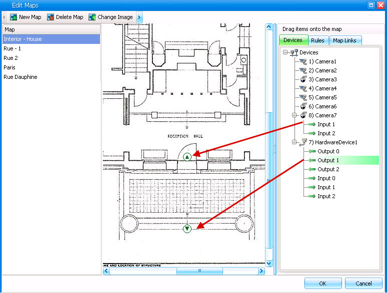
The Map Configuration dialog box contains a Devices tab, listing all cameras and digital input and output devices. You can customize digital input and output names to help identify them.


Icon

Icon Description

Represents

ColoursA Indicate

Triangle pointing up in circle

Digital Input

(e.g., person presses a button, which causes an appropriate action in the system)

Green arrow up, white background = not activated


Green arrow up, yellow background = activated

Triangle pointing down in circle

Digital Output

(e.g., motion sensor detects motion and closes a gate)

Green arrow down, white background = not activated


Green arrow down, yellow background = activated
AIf a device is in an Unknown state (map icon is grey), right-click to display the context menu and to activate or deactivate the device.

The Show Digital I/O option on the must be enabled in Device Tree Configuration dialog box for the digital I/O to be displayed, regardless of which specific inputs/outputs are selected. See Customizing the Camera Tree.

To place digital inputs/outputs on the Map:

1       From the View menu, select Map Navigation.

2       Scroll through the maps to select the one which will have rules.

3       In the upper right corner of the Map dialog box, click Edit Maps. The Edit Maps dialog box opens.

4       Click the Devices tab. From the right pane listing the devices, drag and drop the digital devices to the map with your mouse.

5       Click OK to save settings.